Digital Electronics
Logic gates, circuit diagrams, and the Boolean expressions they represent.
Overview
Digital electronics is all about processing binary signals (0s and 1s) using logic gates. Think of these gates as tiny decision-makers that follow specific rules to produce outputs based on their inputs.
Key Concepts:
- Binary Signals: Only two possible states - 0 (OFF/LOW) or 1 (ON/HIGH)
- Logic Gates: Basic building blocks that perform logical operations
- Truth Tables: Show all possible input combinations and their resulting outputs
Key Concepts
Basic Logic Gates
Each gate has a unique symbol and behavior. Let's explore them one by one:
NOT Gate (Inverter)
The simplest gate - it just flips the input:
- A is opposite of X
Example: If a light switch is OFF (0), the NOT gate makes it ON (1)
| A | X |
|---|---|
| 0 | 1 |
| 1 | 0 |
AND Gate
Only outputs 1 if BOTH inputs are 1:
- Like a series circuit - all switches must be ON
- Any 0 input makes the output 0
Example: A security system that needs both a key card AND correct PIN
| A | B | X |
|---|---|---|
| 0 | 0 | 0 |
| 0 | 1 | 0 |
| 1 | 0 | 0 |
| 1 | 1 | 1 |
OR Gate
Outputs 1 if ANY input is 1:
- Like a parallel circuit - any switch being ON works
- Only outputs 0 if all inputs are 0
Example: A house alarm that triggers if ANY sensor detects movement
| A | B | X |
|---|---|---|
| 0 | 0 | 0 |
| 0 | 1 | 1 |
| 1 | 0 | 1 |
| 1 | 1 | 1 |
XOR Gate (Exclusive OR)
Outputs 1 if inputs are DIFFERENT:
- 1 when inputs are different (0,1 or 1,0)
- 0 when inputs are same (0,0 or 1,1)
Example: A light controlled by two switches - it's ON only if switches are in different positions
| A | B | X |
|---|---|---|
| 0 | 0 | 0 |
| 0 | 1 | 1 |
| 1 | 0 | 1 |
| 1 | 1 | 0 |
Inverted Gates
Any gate can be turned into its inverse by adding a small circle (bubble) at its output:
- AND → NAND: Output is opposite of AND gate (1 unless both inputs are 1)
- OR → NOR: Output is opposite of OR gate (1 only when both inputs are 0)
- XOR → XNOR: Output is opposite of XOR gate (1 when inputs are the same)
AND becomes NAND
The bubble means "NOT" - it inverts the output of whatever gate it's attached to.
Examples
Combining Gates
Gates can be connected to create more complex circuits. The output of one gate becomes the input for another.
This security system has three components:
- Access Verification (First AND + NOT Gates):
- AND gate checks if both key card AND PIN are provided
- NOT gate inverts this - output is 1 for unauthorized access
- Intrusion Detection (Bottom OR Gate):
- Monitors detection of either motion OR window sensors
- Output is 1 if either sensor detects intrusion
- Alarm Trigger (Final OR Gate):
- Triggers if EITHER unauthorized access OR intrusion is detected
- Output is 1 if any input is 1
Practice Problems
For expression answers, use + for OR, write AND as juxtaposition or with * (for example AB or A*B), and use an apostrophe for NOT (for example A').
Problem 1 Junior
Simplify the Boolean expression represented by this circuit using the fewest numbers of parentheses:
Solution
- Let's break down the circuit from inputs to output:
- Input A splits to both AND gates
- Input B goes to top AND gate and through NOT gate to bottom AND gate
- Both AND outputs combine in the OR gate
- Writing the initial expression:
- Top AND: (A·B)
- Bottom AND: (A·B)
- OR combines these: (A·B) + (A·B)
- Simplifying the expression (See Boolean Algebra Laws →):
- Start with: (A·B) + (A·B)
- Factor out A: A(B + B)
- B + B = 1 (complement law)
- Therefore: A(1) = A
- The final simplified expression is: A
Problem 2 Junior
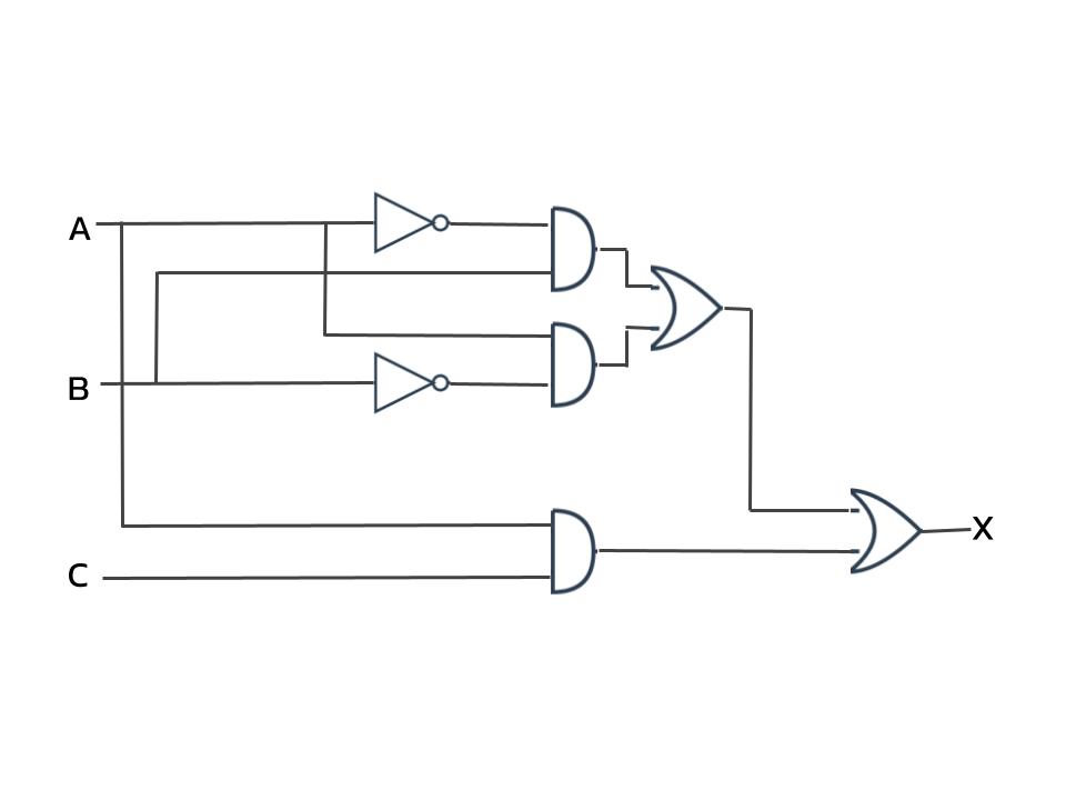
How many ordered triples make the Boolean expression for this circuit FALSE?
Solution
- Let's break down the circuit from inputs to output:
- Top path: (A·B)
- Middle path: (B·A)
- Bottom path: (A·C)
- Final expression: (A·B) + (B·A) + (A·C)
- Simplifying the expression:
- The first two terms form an XOR between A and B
- Therefore: (A⊕B) + A·C
- Finding when (A⊕B) + A·C is FALSE:
- Expression is FALSE when both (A⊕B) = 0 and (A·C) = 0
- This occurs when A and B are the same (for XOR=0) AND either A=0 or C=0
- When A=0: B must be 0, C can be 0 or 1 (2 triples)
- When A=1: B must be 1, C must be 0 (1 triple)
- Total: 3 triples make it FALSE
- The answer is: 3
Problem 3 Intermediate
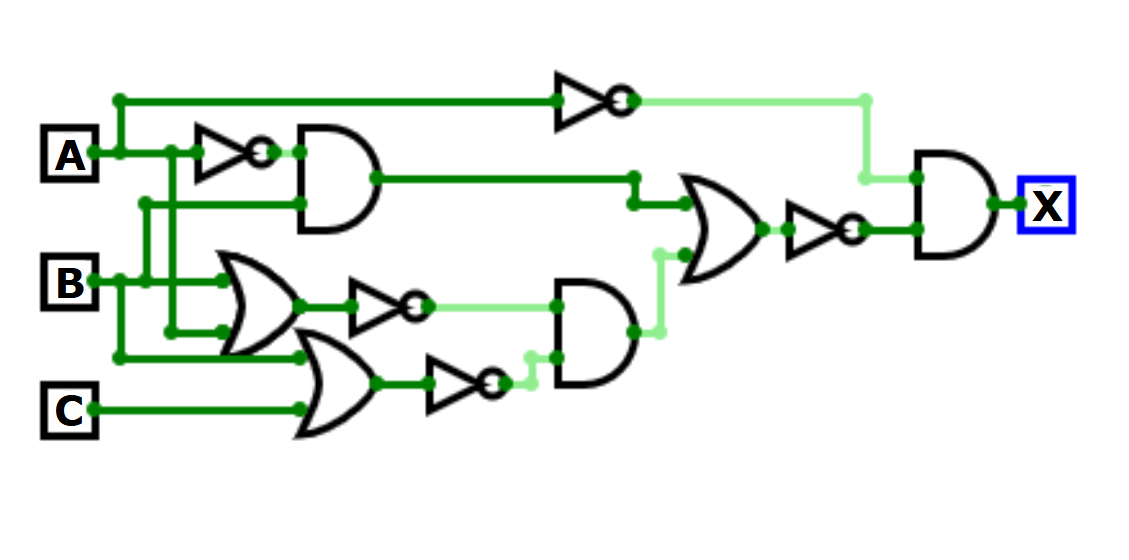
How many ordered triples make this circuit TRUE?
Solution
- The circuit can be expressed as:
- NOT(A) · NOT[(NOT(A)·B) + (NOT(B+A) · NOT(B+C))]
- Let's analyze when this could be TRUE:
- First term: NOT(A) must be 1, so A must be 0
- When A = 0:
- NOT(A)·B becomes B
- NOT(B+A) becomes NOT(B)
- Expression becomes: 1 · NOT[B + (NOT(B) · NOT(B+C))]
- For any values of B and C:
- If B = 0: NOT(B) = 1, and NOT(B+C) will be 1 when C = 0
- If B = 1: First term is 1, second term is 0
- In all cases, the expression inside NOT[] is never 0
- Therefore:
- The expression is always FALSE for all input combinations
- No ordered triple (A,B,C) makes this circuit TRUE
- The answer is: 0
Problem 4 Intermediate
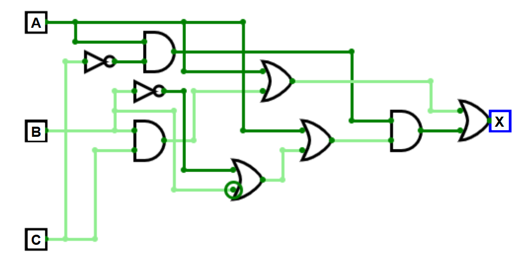
Simplify the Boolean expression represented by this circuit using the fewest numbers of parentheses:
Solution
- Starting expression: ((A + (B·C)) + (A·C))·(A + B + B)
- Let's simplify each part:
- First, the right side: (A + B + B)
- B + B = 1 (complement law)
- So A + B + B = A + 1 = 1
- Now the left side: (A + (B·C)) + (A·C)
- Distribute A: A + (B·C) + (A·C)
- Since A appears alone, any term with A is redundant
- Therefore: A + (B·C)
- Combining both sides:
- (A + (B·C))·1
- Simplifies to: A + (B·C)
- The final simplified expression is: A + B·C
Problem 5 Senior
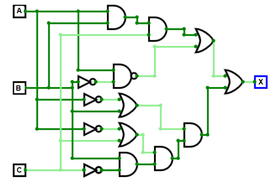
How many ordered triples make the Boolean expression for this circuit FALSE?
Solution
- Starting expression: !(A·!B) + (B·!C)·((!A + C)·(B + !A)) + (A·B·C)
- Let's simplify each part:
- Part 1: !(A·!B) = !A + B (DeMorgan's Law)
- Part 2: (B·!C)·((!A + C)·(B + !A))
- Expand (!A + C)·(B + !A)
- = (!A·B) + (!A·!A) + (C·B) + (C·!A)
- = (!A·B) + !A + (C·B) + (C·!A)
- When multiplied by (B·!C): Most terms become 0
- Simplifies to: B·!C·!A
- Part 3: A·B·C remains as is
- Combining all parts:
- (!A + B) + (B·!C·!A) + (A·B·C)
- This is TRUE in most cases except when:
- - A is 1 (negating first term)
- - B is 0 (negating first term)
- - C is 1 (negating second term)
- And A·B·C = 0
- Finding FALSE cases:
- When A=1, B=0: C can be 0 (1 case)
- When A=0, B=0: C can be 1 (1 case)
- The answer is: 2